
What is the Lifespan of a Flexible PCB?
Flexible PCB
A flexible circuit board is a great way to incorporate rigid and flex components into a product. These types of circuit boards can be bent up to a certain degree, and they also have the capability to endure high temperatures and harsh environments. Ultimately, these features allow for a longer lifespan and greater durability.
The lifespan of a flexible circuit board is determined by its design and construction. A key factor in determining this is the material used for the substrate. Most commonly, FR-4 is used. However, polyimide is also an option. It is more expensive than FR-4, but it offers higher flexibility and resistance to environmental factors.
Another important factor is the type of copper that is used in a flexible circuit board. Rolled annealed copper is preferred, as it can withstand more bending and rolling than other options. In addition, it can withstand higher temperature levels, which is essential for many applications.
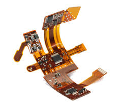
What is the Lifespan of a Flexible PCB?
Rigid flex circuits can be created from various materials, including aluminum, electrodeposited (ED) copper, and even conductive ink. The choice of material depends on a variety of factors, such as cost, thickness, and conductivity. A good CM will work with their customers to determine which material is best for the application.
When designing a flexible PCB, it is important to consider the number of times it will be bent during its lifetime and how much it will flex at each bend point. A static flex board will be less rigid and may only flex 100 or so times in its life. A dynamic flex board will need to withstand tens of thousands of bends over time.
The type of coverlay, flexible solder mask, stiffeners, and adhesives used in a flex circuit will also impact the lifespan. For example, some of these materials can increase the amount of stress that is placed on the traces. To avoid this, it is necessary to avoid 90-degree bends and to stagger traces on multi-layered circuits. In addition, a flex circuit should be designed so that the neutral axis is perpendicular to the bend axis.
A final consideration is how a flex circuit will be soldered. Ideally, the solder joints will be minimal and close to the component leads. This reduces the chance of solder shorts and increases reliability. The flex circuit should also be tested before assembly to make sure that it is working correctly. Lastly, an electromagnetic interference (EMI) shielding film can be added to the flexible PCB for additional protection.